Version 2.0 (17/4/2004)
1 The Diesel Engine
2 Theory of Vegetable Oil Use as
a Fuel
3 Engine suitability
4 Heating the Oil
5 Biodiesel
6 Micro Emulsions and Blends
7 Vegetable Oil Engine Design
8 Vegetable Oil Furnaces and Heaters
9 Oil Types and Filtering
10 Taxation
11 Implications of Vegetable
Oil Fuel Use
12 Sources
The Diesel Engine
Dr. Diesel
The term diesel derived from a German engineer, Dr Rudolph
Diesel, who is widely credited with developing the compression
ignition (CI) engine. In 1892 he took out a patent (no.7241)
on a CI engine which ran on coal dust this was built in
1893 but exploded when it was run.
In 1894 he filed a patent for a CI oil engine which he
successfully ran in 1897. In 1900, at the world fair in
Paris, a small diesel engine was demonstrated running on
peanut oil. The Otto Company provided this demonstration
at the request of the French Government which was keen to
use peanut oil as an energy source for its African colonies.
There is however some controversy as to weather he was
the inventor of this type of engine as a British engineer,
Herbert Ackroyd-Stuart took a patent (No.7146) in 1890 for
an oil fired engine which was the result of development
he had been doing on low-compression oil engines. This patent
describes "first of all compressing the necessary quantity
of air for the charge, and then introducing into this quantity
of compressed air the necessary supply of combustible liquid,
vapour or gas, to produce the explosive mixture." The
engine was in production in 1892. Also Ruston & Hornsby
Ltd claimed, in a 1937 advertisement “Before Dr. Diesel
took out his first oil engine patent, we were making successful
oil engines at our Granthan Works.”
As the engine could be fuelled on a variety of oil fuels,
Dr. Diesel saw his engine as a way of freeing small producers
from the grip the steam industry had on the energy markets
of the time. He worked on the development of the engine
until his untimely death. Much controversy surrounds his
death on board a boat to England some say he committed suicide,
others suggest an accident, others still that something
more sinister was afoot.
Due to economics fossil oil became the energy sources of
choice for the developed nations and a distillate of crude
that was suitable for CI engines came to be known as diesel
fuel. CI engine development since this time has largely
been with diesel fuel in mind. Most CI engines are engineered
to optimise the burning of this fuel. It is however possible
to tune these engines so that they can be fuelled with vegetable
oil.
C.I. Engine Basic Principles
Diesel engines come in all shapes and sizes with refinements
made to the basic principles developed in the late 19th
century.
The Direct Injection Engine (DI)
The engine uses the heat caused by compressing air in a
cylinder, with a piston, to ignite fuel oil which is injected
into the cylinder. This oil burns and creates an increase
in pressure which forces the piston back down the cylinder,
providing the power. The burnt gasses are exhausted from
the cylinder and replaced by fresh charge through valves,
commonly positioned above the piston in the cylinder head.
The fuel oil is pushed into the engine under high pressure
at the correct time by an injector pump. The oil is sprayed
into the engine cylinder as a very fine mist from the nozzle
of an injector. The fine fuel oil mist readily mixes with
hot air in the cylinder, ignites and provides an efficient
burn. The injector pump also meters the amount of fuel delivered.
The more fuel the more power/faster the engine.
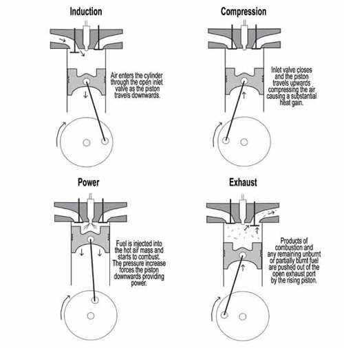
Operating cycle of the common four stroke engine –
the engine provides one combustion event during the four
piston strokes illustrated.
Large DI Engines
Large slow running DI engines (under 1500 rpm) commonly
used to power machinery and large boats have 'open chambers'
where the piston has a wide shallow dish in the centre of
its upper surface. Air movement within the combustion chamber
is minimal and the multi-hole injectors (often 8-12 holes)
are set to inject a fine mist into the dish. Due to the
size of the combustion chamber and the distribution of fuel
sufficient air is present to supply the fuel with sufficient
oxygen and the fuel combusts before it contacts surfaces
of the combustion chamber.
Small DI Engines
Small high speed direct injection engines
have a deep hollow in the top of the piston which contains
most of the air when the piston is at the top of the engine.
As air is drawn into the engine a swirling motion is initiated.
The air is forced into a horizontal rotary motion by the
design of the air inlet port or valve. Some engines have
a helical or partial vortex form of inlet port to encourage
the swirl in others the inlet valve is partially masked
to initiate the desired motion. As compression of the air
begins it is forced or squished into the specially shaped
piston hollow which initiates a vertical swirl achieving
ever increasing speeds and heat as the air is compressed.
These combined movements create an air vortex within the
piston into which the fuel is injected. The fuel spray,
finely atomised by the high-pressure injector, passes through
this air vortex where it is provided with sufficient oxygen
and heat to combust. DI engines generally utilise a multi-hole
injector to provide a good distribution of fuel.
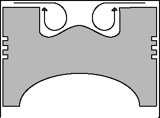
Squish air motion in a DI engine
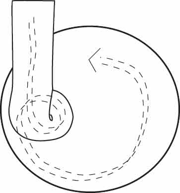
Air spiralling through a helical intake
into engine cylinder
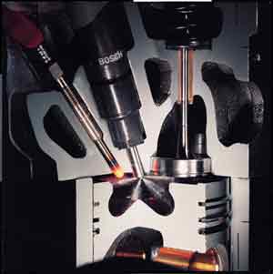
Photo: Bosch
Cut away view of a
small DI cylinder
The Indirect Injection Engine (IDI)
A later development was the IDI engine that utilises a
separate combustion chamber, connected to the engine cylinder,
into which the fuel is injected and combustion is initiated.
A heat resistant insert with low heat conductivity is located
within the combustion chamber so it quickly heats up and
retains heat from combustion, providing extra heat to enable
quicker ignition. The fuel is injected into the hot combustion
chamber as a jet at a low pressure compared to the fine
high-pressure spray of a DI engine. The fuel jet hits the
hot insert where ignition is initiated; the fuel is distributed
around the combustion chamber as combustion continues. The
expanding burning fuel, along with partially burnt and unburnt
fuel, is carried into the hot engine cylinder where further
oxygen is available and combustion continues.
The most common prechamber format utilised is the Ricardo
Comet design developed by Ricardo and Company of Shoreham,
Sussex, UK. With this design air is pushed from the cylinder
into a circular ‘swirl chamber’ through a tangentially
aligned throat. The bottom half of the chamber along with
the throat is constructed from a nimonic alloy designed
to maintain high temperatures during engine operation. The
temperature of the compressed air is raised further while
passing through the throat. A vigorous swirl motion is initiated
as the air is forced into the circular swirl chamber. The
fuel is injected into the swirl chamber and rapidly atomised
within the mass of hot turbulent air.

Photo:Bosch
IDI engine – Picture shows fuel being injected into
a swirl chamber with a heated glow plug – not shown
is the throat from the engine cylinder to the swirl chamber
- Note the lower half of the chamber constructed from nimonic
alloy.
Mercedes IDI engines utilised a different design in which
a jet of fuel is fired at a ball like baffle surface. The
jet is broken by the baffle surface and distributed around
the prechamber being finely dispersed by the turbulent air
charge. Upon combustion the fuel/air mixture is carried
through several bores into the main engine cylinder. Mercedes
later improved this design, reshaping the prechamber, creating
a swirling air motion to improve combustion.
The advantage of IDI engines is that they can operate at
higher engine speeds as the more efficient fuel and air
mixing provides faster combustion. Cars and small commercial
vehicles require a small, light engine which must be able
to operate at higher speeds to provide the necessary power,
with the advent of the IDI engine the use of diesel engines
in such vehicles became widespread.
The heat lost due to the increased surface areas of the
combustion chamber and the pressure drop between cylinder
and combustion chamber make it necessary for the engines
to operate at higher compression ratios to provide enough
heat for ignition. The lost heat and force required to push
the air into the combustion chamber is wasted energy making
IDI engines around 10-15% less efficient than DI units.
IDI engines became the engine of choice in small vehicle
applications as a small engine could produce more power
at higher speed providing a suitable power/weight ratio
for such applications. Recent advances in fuel injection
technology, which provide more precise fuel delivery, allow
faster combustion within a DI engine. The improved efficiency
of the DI cycle has spurred the fitment of such engines
to become more common in small vehicles.
Fuel Injection Equipment
Timing, pressure and quantity of fuel delivery are crucial
for efficient combustion. The important task of fuel delivery
is performed by the fuel injection equipment.
Mechanically Controlled Fuel Injection
Fuel is supplied to the injector by an injector pump.
The injector pumps are mechanically driven from the crankshaft.
The drive from the crankshaft is set so that the injector
pump delivers fuel at the correct time in the engine operation
cycle.
Single Element Injection Pump (Jerk Pump)
The simplest type of injection pump found on single cylinder
engines. The single pumping element delivers fuel to the
injector via a high pressure pipe. Multi-cylinder engines
sometimes utilise multiple single element pumps. This is
most often seen in stationary or marine applications.
In-Line Injector Pump
In-line pumps use a similar design to the single element
pump, for a multi-cylinder engine. A number of jerk pumps
are combined into a single component. The pumps are driven
by a camshaft held within the pump body.
Rotary Injector Pump
Rotary pumps are similar in appearance to a petrol engine
distributor. A single pumping mechanism rotates and supplies
fuel to each cylinder in turn.
Electronically Controlled Fuel Injection
Recently developed electronically controlled injectors can
provide exacting amounts of fuel at very high pressure,
very precise timing and even multiple injections within
each cycle to give greatly improved combustion and in turn
increased fuel economy and lower engine noise and toxic
emissions. Both in-line and rotary injection pumps have
been developed with electronic components to help achieve
more accurate injection timing and metering. By monitoring
the engine using a number of sensors the electronic controller
can modify the fuel injection characteristics to improve
combustion.
Common Rail Injection Systems (CDI)
With this system a pump constantly supplies fuel at a
very high pressure to the common rail - a tube with thick
walls. From the common rail fuel is supplied to electronically
controlled injectors.
The higher pressure injection gives a finer spray and improved
combustion.
Unit Injector System and Unit Pump Systems
Unit injector systems combine the pump and injector into
one unit. The pump is driven from the engines camshaft.
Fuel delivery is timed and metered by electronically controlled
valves. Unit pump systems are similar with the pump and
injector separated and connected by a short high pressure
fuel line.
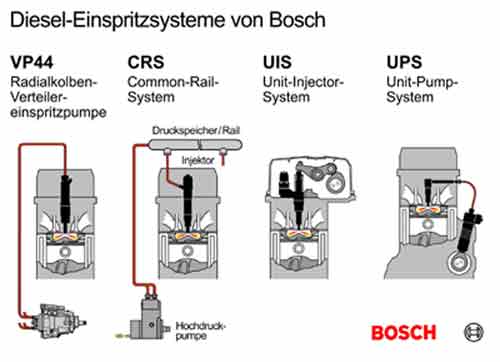
Diagram: Bosch
Bosch Electronic Injection Systems:
Illustration shows a VP44 electronically controlled rotary
pump and 3 other systems
Turbocharger
Diesel engines are particularly suited to turbocharging.
Turbochargers use a specially designed turbine and centrifugal
compressor linked by a shaft to utilise the energy of the
exhaust gas being forced from the engine to compress extra
air into the engine. The compressed air contains more oxygen.
The amount of fuel that can be effectively combusted is
directly proportionate to the amount of oxygen within the
engine. Thus the maximum fuel delivery can be adjusted and
engine power increased by as much as 60%. Due to more efficient
combustion fuel efficiency is improved by about 10%. Turbocharged
engines are generally of a more rugged construction to withstand
the greater forces and temperatures encountered.
Intercooler
Intercoolers are often added to turbo engines to cool
the air charge between the turbocharger and the engine.
Compression of the air and proximity to the hot exhaust
gases increase the temperature of the air charge and cause
it to expand. The intercooler, most often an air to air
heat exchanger, uses air flow in the same way as an automobiles
radiator to bring the temperature of the air charge down.
The cooled air contracts and more of it – and thus
more oxygen – can be forced into the engine cylinder.
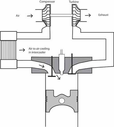
Turbocharged and intercooled engine.
Combustion in a Diesel Engine with Mechanical Fuel Injection
System
The combustion process is initiated when the fuel is injected
into hot air within the combustion chamber. The temperature
reached in the combustion chamber will be effected by;
compression ratio : the more the air is
compressed the higher the pressure and the hotter it becomes
the speed of the engine : the faster the
air is compressed the less time there is for heat to be
lost from the combustion chamber and air to seep by the
piston rings reducing the pressure.
the temperature of the incoming air
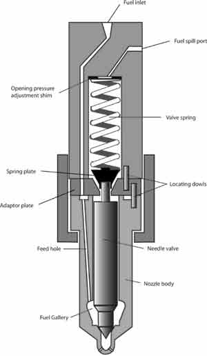
The fuel is delivered by the injector pump pushing fuel
through the injector. The pumping action produces a rise
in pressure in the fuel line as the pressure rises it overcomes
a spring which holds the injector needle valve closed. The
injection lag is the time between the pump pumping and the
fuel being delivered and is affected by the length of the
high pressure injection pipe, the load on the injector spring
and the density and thus compressibility of the fuel.
The fuel is injected into the hot air mass
within the combustion chamber by the injector which delivers
a fine spray of fuel. This spray breaks into small droplets
which begin to evaporate in the intense heat. Each droplet
becomes surrounded by a layer of vapour which begins to
react with the surrounding oxygen. For any delivered amount
of fuel, the finer the spray, the larger the surface area
of fuel available to vaporise and then react with oxygen.
However a fine spray will not penetrate far into the combustion
chamber where further oxygen would be available and would
be easily dragged around with any air flow which would otherwise
be introducing further oxygen. A spray of large droplets
would travel further through the combustion chamber less
affected by air motion but would take longer to ignite and
longer to combust entirely.
Multi Hole Injector
The oxidation process creates heat which causes more vaporisation
and increased oxidation until the self-ignition temperature
of the fuel is reached and, at a limited number of points
within the chamber, ignition of the vapour begins. The time
between the fuel being introduced and start of ignition
is called the ignition lag or delay period.
Combustion then spreads quickly through the fuel which
has been injected during ignition lag causing a rapid pressure
rise. A long ignition lag allows a greater amount of fuel
to be delivered which will cause a more rapid and greater
pressure. The increased engine noise and rough running ,known
as diesel knock, is a direct result of these greater pressures.
The rate of burn will depend on the speed at which the vaporising
fuel droplet can come into contact with unreacted oxygen.
The speed of the fuel and motion of the air, if any, affect
the burn rate. The rapid pressure rise continues, slowing
as the temperature increases to a level where fuel droplets
are burnt soon after being injected.
At each fuel droplet the liquid oxidation reaction of
the vapour will continue rapidly as long as sufficient oxygen
is available. As the combustion continues less oxygen is
available close to the injector and the fuel droplets take
longer to find enough oxygen to burn. Combustion continues
at a steady level until the fuel delivery is completed.
The remaining fuel and unburnt products of the oxidation
reaction continue to burn with decreasing vigour as the
temperature in the chamber falls. Some of these products
remain unburnt and are largely expelled with the exhaust.
1 The Diesel Engine
2 Theory of Vegetable Oil Use as
a Fuel
3 Engine suitability
4 Heating the Oil
5 Biodiesel
6 Micro Emulsions and Blends
7 Vegetable Oil Engine Design
8 Vegetable Oil Furnaces and Heaters
9 Oil Types and Filtering
10 Taxation
11 Implications of Vegetable
Oil Fuel Use
12 Sources